Breadboarding Time
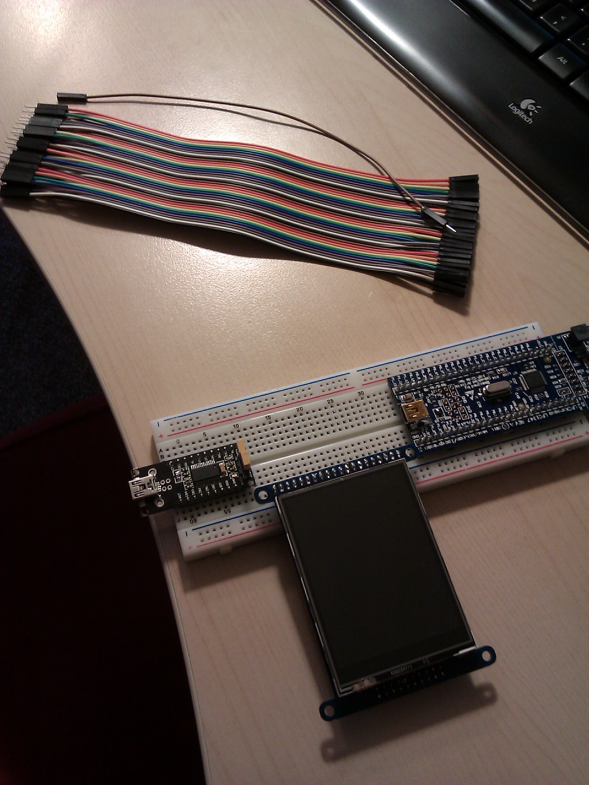
Mar 15 2014Jumper wires arrived from ebay yesterday, but I was working on Lanyon-Hugo so I didn't start breadboarding until now. Here's a picture of the three main players: the LPCXpresso (we only care about the target half), the serial adapter (mine is an FT232RL from ebay) and the ILI9325 breakout (which we'll discuss in the next post). Major note: your serial adapter should have 3.3V IO, not 5V! You could damage your micro exposing it to 5V signals carelessly. Most FT232RL adapters have a solder jumper to set the IO voltage; mine has a header jumper which is a nice bonus since I don't own my own iron.

Let's start at the beginning: programming the board. I'm using the codebase's default main function, which just blinks LED2 (classic blinky example). You can check out the code base in its original state (development branch), then run make all to generate a firmware.hex and open up Flash Magic.
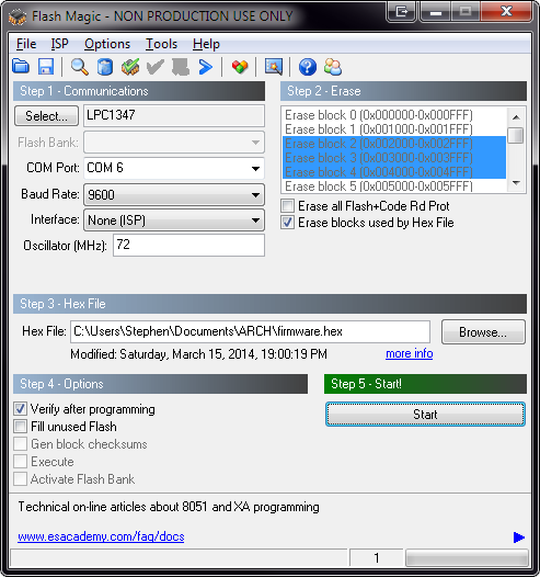
This screenshot shows the basic settings. In particular, COM6 should be set to the COM port of your serial adapter (whatever that may be), and the oscillator should be 72MHz, which is the core clock frequency of the target on the LPCXpresso board. You can increase the baud rate once you have it working, the system uses autobaud to determine what the communication speed is. However, you should stay at a low setting when you're getting started, just in case your hardware doesn't like the higher speeds.

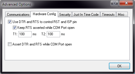
Now, for the connections. I'm not going to make this a tutorial for UARTs in general, so you should already know what to do with the TX/RX and power pins. However, programming with Flash Magic needs a bit more than that. Open up Flash Magic's Advanced Options dialog box. On the Hardware Config tab, turn on DTR/RTS control, like so. The T1 time in this screenshot is a bit long (I think it's 50ms default), but the default times should be fine.

Your serial adapter needs to have both DTR and RTS broken out. A lot of common adapters, like the Adafruit FTDI Friend, only expose one of these at a time. This is motivated by the design of the Arduino. But in this case, we need DTR and RTS at the same time. My adapter breaks out pretty much all the pins, so yay for me. Connect DTR to P0_0 (reset pin) and connect RTS to P0_1 (ISP pin).
What does this do? If ISP is asserted (P0_1 held low) while the microcontroller is in reset (P0_0 held low), it will enter programming mode. The Flash Magic Advanced Options dialog allows us to control those two signals via DTR and RTS, which we have just connected.
There is one more thing you have to do! Connect P0_3 to ground. This pin is tied to the LPC1347's USB_VBUS signal. The idea is that, if a USB cable is plugged in, then the signal gets pulled high. Otherwise, it's supposed to be pulled low. When the microcontroller enters ISP mode, it can either program over the serial port or over USB. It determines which one to use from the state of P0_3. We want it to use the serial port, so we have to indicate that USB is not connected, by holding this signal low.
If you need more detailed explanations of all of this stuff, you can find it in the LPC1347 user manual (the NXP document number is UM10524), chapter 21. You might also want to refer to Flash Magic's manual, which you can find on the Help menu of Flash Magic. The user manual for the LPC1347 is really intimidating, but trust me, you can learn a lot by reading it.
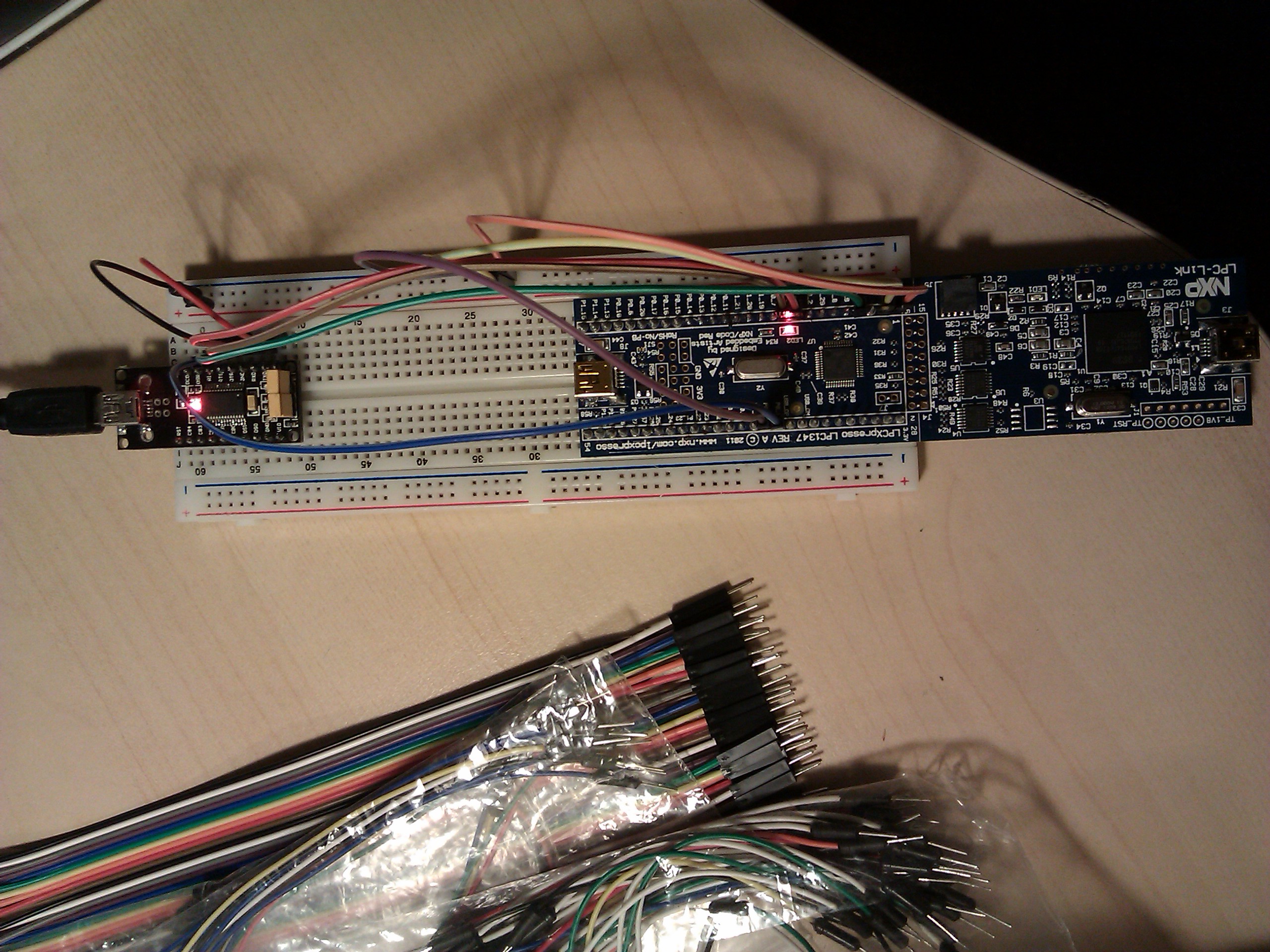
Here is a picture of the final breadboard with all the connections. (Yeah, it's not very useful. I might make a quick schematic showing this stuff in the future.)

Now, if you press Start on Flash Magic to initiate programming, you should be successful. If you still get autobaud failures, the first thing you should try is swap your TX/RX pins (some adapters are quirky and have them the other way around). Make sure you grounded the VBUS pin like I said; I wasted 20 minutes trying to figure that one out.
Programming can be pretty slow at 9600 baud, so feel free to turn it up a bit. My setup is reliable at 115200 baud (and it's WAY faster, obviously), but if your hardware is finicky, then you might not be as lucky.
That was surprisingly tricky, eh? There's more to a serial port than TX and RX, but most applications don't use all the control signals. Plus, there's no way you'd find out about that VBUS thing unless you read the manual. Next post, I'll show you how to connect the ILI9325 breakout board, and then it'll be time for some real development action.