04 Apr 2014
It's been a grim week. The end of lectures approaches, and with it, exams. As usual, I am lazy and not doing my work or studying. But I haven't felt this satisfied in... at least the last two months. My ILI9325 driver is officially functional.
I know I promised a post on breadboarding the LCD but that's not important right now, because the driver works! Let me give you some development background. I think every line of code tells a story, and heaven knows we all love telling stories about ourselves.
The LPC13xx codebase did not have an ILI9325 driver to start, but it did have an HX8347 driver. The chips are not compatible, although I often see them referred to in the same breath because they have a similar interface, and because they are among the most common LCD drivers for hobbyists. Generally they're both 2.8" 320x240 with resistive touchscreens, and they feature an 8-bit 8080 interface (or 16-bit, sometimes even 18-bit, depending on the board you get).
TFT drivers are a complicated business so there's a lot of configuration to go around, hence the HX8347 driver couldn't be shoved directly into an ILI9325-driven TFT. Luckily, the predecessor of the LPC13xx codebase (targeting the older LPC1343) did have a driver for this chip. So let me be honest and admit that most of the code I've been working on came from that driver. The logic to drive an 8080 bus, plus the configuration sequences, was in that older driver and my work wouldn't have been possible without it.
The main effort was modifying the GPIO accesses. The LPC1343 and LPC1347 use different GPIO blocks, so the register interfaces are fundamentally incompatible. My contribution to the driver is the use of the LPC1347's GPIO masking feature. This lets you designate a mask over the GPIOs of a port. The mask is paired with a masked port register; reads and writes to this register can only affect bits that are cleared in the mask. This makes it pretty easy to write the 8 data bits in a single move. (Although if you look at my commit history, you'd think I was pretty incompetent, stumbling around this feature. I don't know why it took this long to figure out tbh, I added the masking pretty early on.)
Anyway, as proof of my triumph, check out this fabulous blue color:
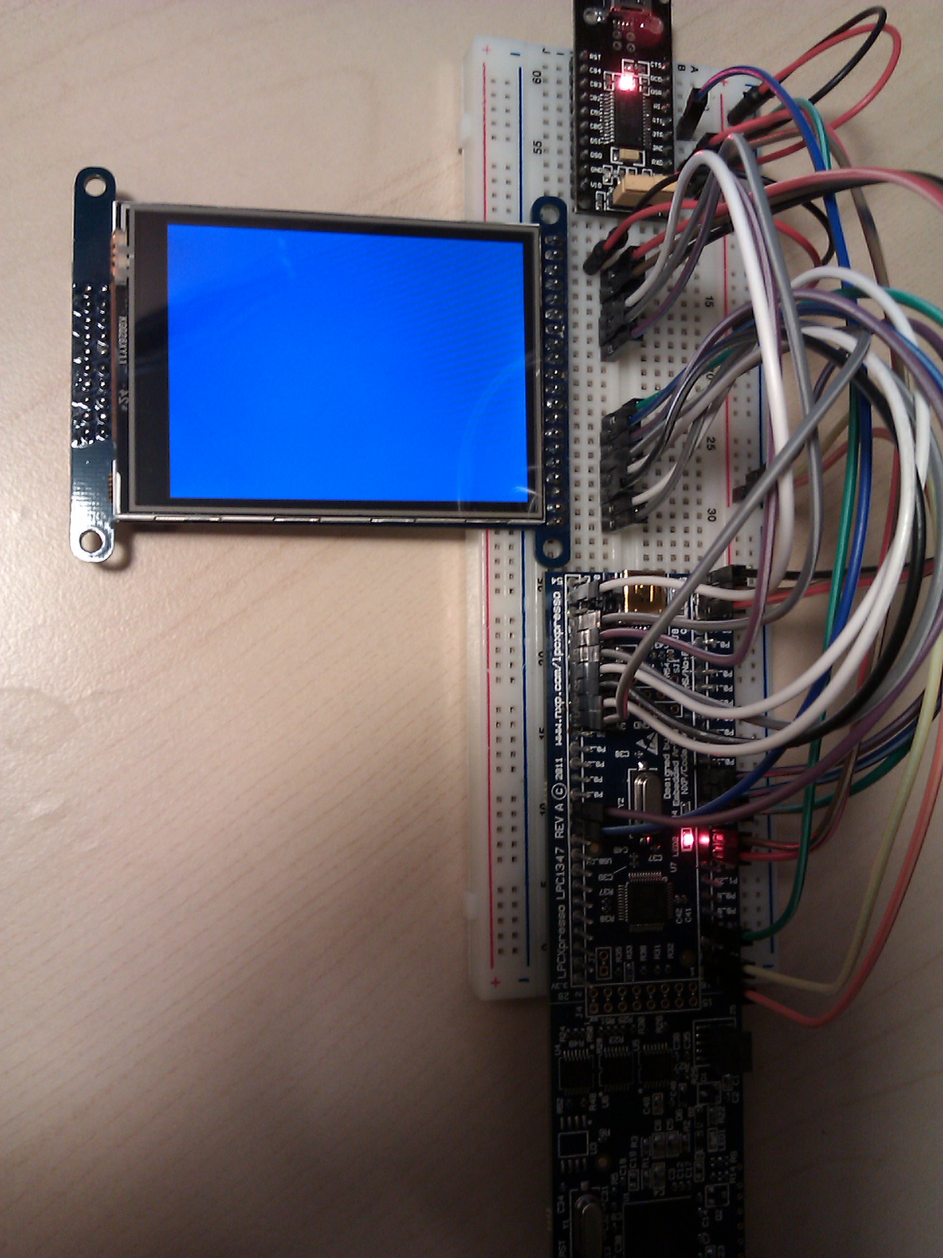
You can see the breadboarding for the screen. It's honestly quite straightforward. If you look at ili9325.h you'll see the pinouts, clear as day. I might make a schematic fragment to illustrate the connections more clearly later, but right now all I care about is that beautiful blue. (The code is actually alternating blue and red, in sync with the blinky LED, for maximum evidence that it works. You can see the LED is also on in this picture. The cycling between blue and red is pretty quick, and this code is deeply optimized from the previous codebase already, so speed shouldn't be a big problem yet.)
15 Mar 2014
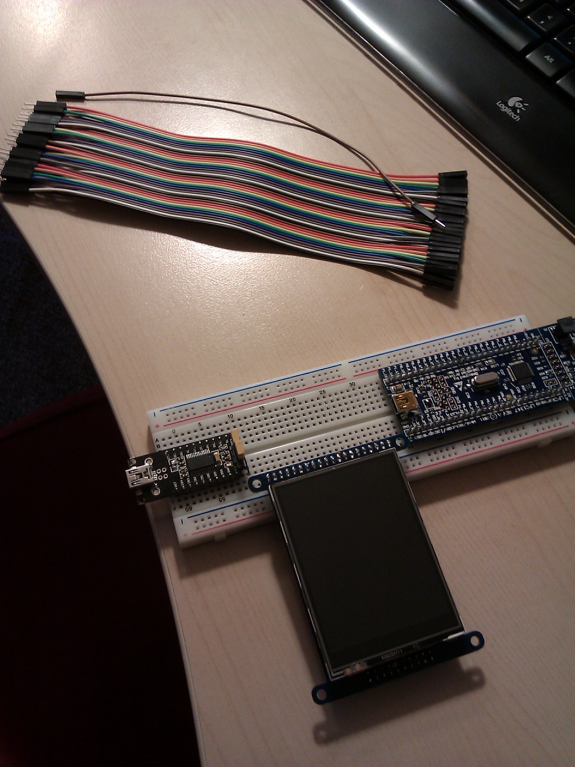
Jumper wires arrived from ebay yesterday, but I was working on Lanyon-Hugo so I didn't start breadboarding until now. Here's a picture of the three main players: the LPCXpresso (we only care about the target half), the serial adapter (mine is an FT232RL from ebay) and the ILI9325 breakout (which we'll discuss in the next post). Major note: your serial adapter should have 3.3V IO, not 5V! You could damage your micro exposing it to 5V signals carelessly. Most FT232RL adapters have a solder jumper to set the IO voltage; mine has a header jumper which is a nice bonus since I don't own my own iron.
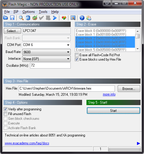
Let's start at the beginning: programming the board. I'm using the codebase's default main function, which just blinks LED2 (classic blinky example). You can check out the code base in its original state (development branch), then run make all to generate a firmware.hex and open up Flash Magic.
This screenshot shows the basic settings. In particular, COM6 should be set to the COM port of your serial adapter (whatever that may be), and the oscillator should be 72MHz, which is the core clock frequency of the target on the LPCXpresso board. You can increase the baud rate once you have it working, the system uses autobaud to determine what the communication speed is. However, you should stay at a low setting when you're getting started, just in case your hardware doesn't like the higher speeds.
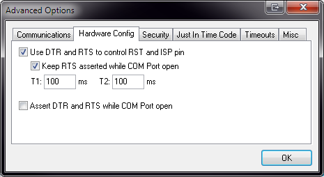
Now, for the connections. I'm not going to make this a tutorial for UARTs in general, so you should already know what to do with the TX/RX and power pins. However, programming with Flash Magic needs a bit more than that. Open up Flash Magic's Advanced Options dialog box. On the Hardware Config tab, turn on DTR/RTS control, like so. The T1 time in this screenshot is a bit long (I think it's 50ms default), but the default times should be fine.
Your serial adapter needs to have both DTR and RTS broken out. A lot of common adapters, like the Adafruit FTDI Friend, only expose one of these at a time. This is motivated by the design of the Arduino. But in this case, we need DTR and RTS at the same time. My adapter breaks out pretty much all the pins, so yay for me. Connect DTR to P0_0 (reset pin) and connect RTS to P0_1 (ISP pin).
What does this do? If ISP is asserted (P0_1 held low) while the microcontroller is in reset (P0_0 held low), it will enter programming mode. The Flash Magic Advanced Options dialog allows us to control those two signals via DTR and RTS, which we have just connected.
There is one more thing you have to do! Connect P0_3 to ground. This pin is tied to the LPC1347's USB_VBUS signal. The idea is that, if a USB cable is plugged in, then the signal gets pulled high. Otherwise, it's supposed to be pulled low. When the microcontroller enters ISP mode, it can either program over the serial port or over USB. It determines which one to use from the state of P0_3. We want it to use the serial port, so we have to indicate that USB is not connected, by holding this signal low.
If you need more detailed explanations of all of this stuff, you can find it in the LPC1347 user manual (the NXP document number is UM10524), chapter 21. You might also want to refer to Flash Magic's manual, which you can find on the Help menu of Flash Magic. The user manual for the LPC1347 is really intimidating, but trust me, you can learn a lot by reading it.
Here is a picture of the final breadboard with all the connections. (Yeah, it's not very useful. I might make a quick schematic showing this stuff in the future.)
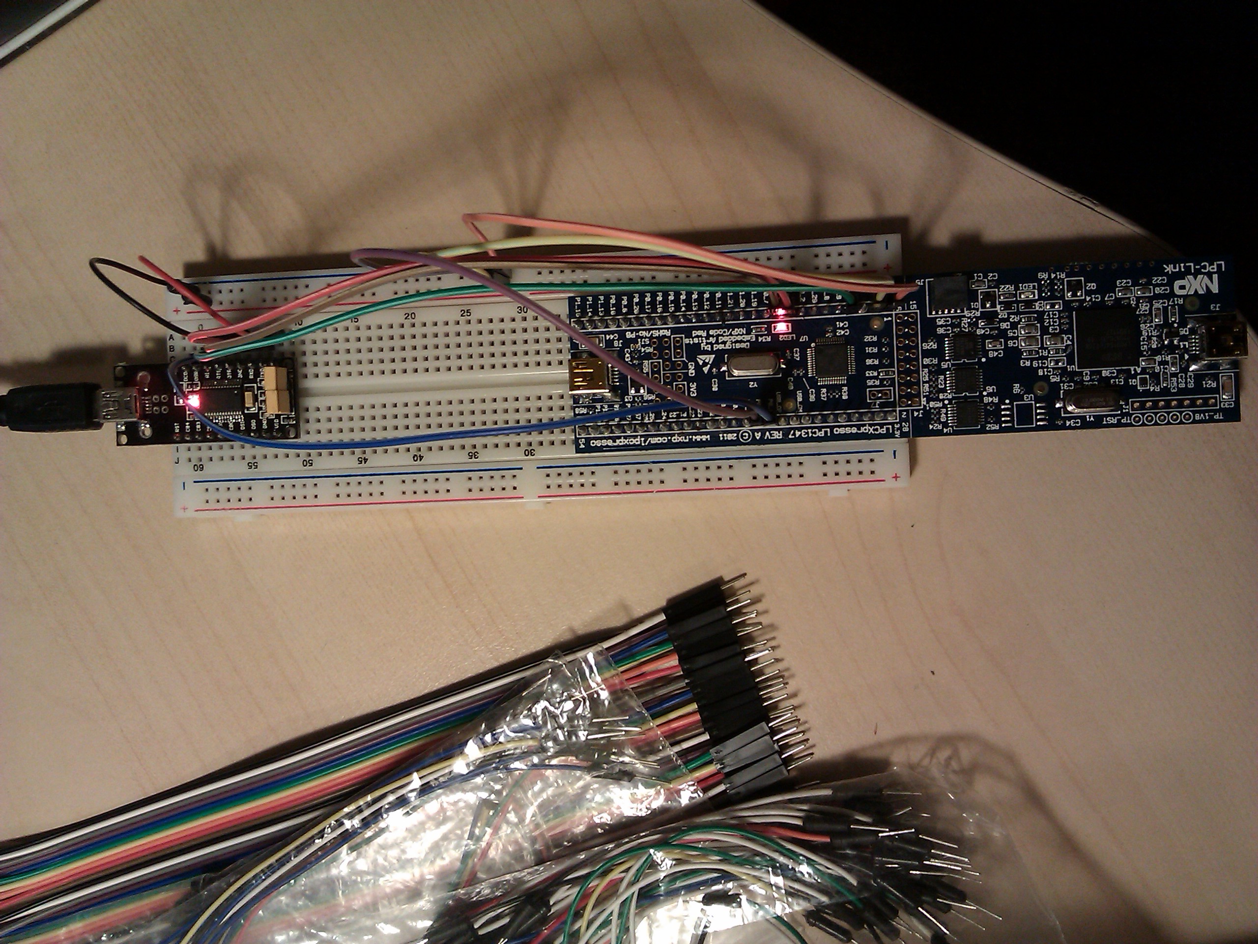
Now, if you press Start on Flash Magic to initiate programming, you should be successful. If you still get autobaud failures, the first thing you should try is swap your TX/RX pins (some adapters are quirky and have them the other way around). Make sure you grounded the VBUS pin like I said; I wasted 20 minutes trying to figure that one out.
Programming can be pretty slow at 9600 baud, so feel free to turn it up a bit. My setup is reliable at 115200 baud (and it's WAY faster, obviously), but if your hardware is finicky, then you might not be as lucky.
That was surprisingly tricky, eh? There's more to a serial port than TX and RX, but most applications don't use all the control signals. Plus, there's no way you'd find out about that VBUS thing unless you read the manual. Next post, I'll show you how to connect the ILI9325 breakout board, and then it'll be time for some real development action.
28 Feb 2014
A few minutes ago, I just committed the design files for the first "ready-to-manufacture" version of my project's case. I had said earlier that the case would be a Sick of Beige case, as designed by Dangerous Prototypes. The case I just committed was not a Sick of Beige size. What gives?
I was planning to use the DP10080 as I had specified earlier, but there was a significant cost premium for that standardized choice. Now I'll explain why I didn't use it and why I designed a custom size instead. For starters, let me show you two pictures. The first is the DP10080 design, and the second is the current smaller design. These pictures are not to scale.
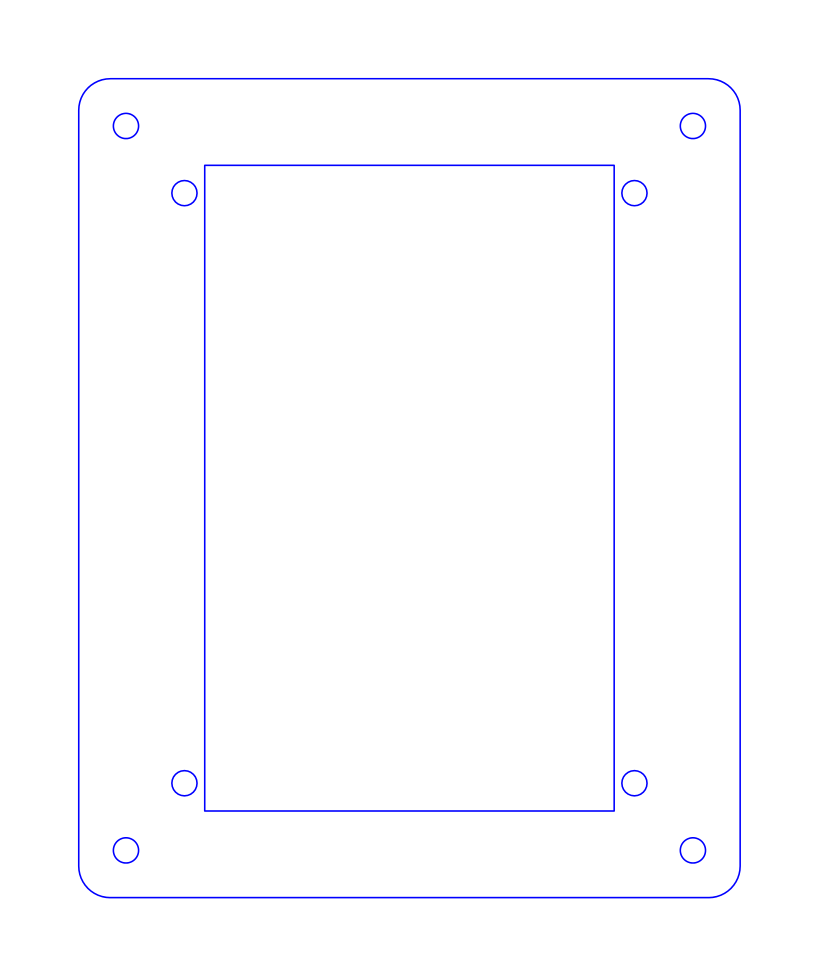

The size of the Adafruit TFT module is rather unfortunate from the standpoint of Seeed Studio's laser cutting service. The holes are separated by 2.95" the long way, and 2.25" the short way (specs). This is too big to fit on the standard DP9056 size of SoB case (the 56mm dimension is too small). In fact, it won't even fit on the DP10062 size (62mm is still too small). It demands the largest, the DP10080 size, which was my original target.
However, Seeed Studio charges a premium when your design goes above a 10x10cm boundary. Upgrading to 20x20cm incurs a significant price markup. The SoB cases are a bit larger than the PCBs they are designed to enclose, so the DP10080 case is a bit more than 10cm in the long direction - big enough to jump from 10x10cm to 20x20cm. Ouch.
As if that wasn't bad enough, there is also a premium for complexity. Designs which have a longer perimeter will need more cutting, which will take more time on the laser cutter, so naturally those designs should be charged more. I agree with this policy completely. Unfortunately, the bigger case has a longer perimeter which bumps up the total length of the laser cut job. Seeed's "easy" benchmark, the minimum cost bracket, is 60cm or less total length. The DP10080 case, with cutouts to mount the Adafruit TFT, had a cutting length of about 72cm.
As of writing, Seeed charges $7.50 for five clear pieces of acrylic, within a 10x10cm boundary, with up to 60cm of cuts. For another five clear pieces of acrylic, but within a 20x20cm boundary, and with up to 180cm of cuts, the price goes up to $21.50 - nearly triple the cost. Ouch. That had to be fixed, so I decided to make a custom case which would use the same design principles as the Sick of Beige templates, but shrunken to the minimum to fit the Adafruit TFT module I was using.
In this design, the acrylic sheet is just large enough to place the four holes for the TFT module. This reduces the size of the design to about 87x69mm, which fits within Seeed's 10x10cm boundary. So that's some significant cost reduction right there. (In the DP10080 version, I was using four holes for the PCB, in the original places shown by the standard size, and then I had another four holes, closer together, for the TFT.)
Both designs also had a large rectangular hole in the center. The TFT uses a ribbon cable to connect to the board, so it needs a routing slot to fit the cable through. This hole adds a fair amount of length to the laser cutting job. However, with the smaller case, the total cutting length dropped to about 58cm, just within Seeed's 60cm limit. So that's some more cost savings.
Overall, the current case design fits within the lowest cost bracket Seeed provides for laser cutting, which was worth the trouble of giving up the standard DP10080 design. It's too bad that there wasn't a Sick of Beige design which was a bit closer to the dimensions I needed, but I guess laser cutting services exist to solve problems like these, so I can live with it.
24 Feb 2014
Should be ordering from Seeed soon. I printed out the PCB layout to scale and checked the footprints with actual parts, so it's ready to be ordered and stuffed. However, I wanted to consolidate that with the laser-cutting order for the case (Sketchup files coming soon), and I encountered some confusion.
Seeed's documentation is not clear about the laser cutter file format. On the specifications, they say to submit EPS/CDR files, but on the actual submission page, they say to submit zip/rar archives (contents unspecified). Below that is an example submission, which is in DWG format. On top of that, an old Dangerous Prototypes tutorial uses SVG files in zip archives. I've emailed support and I don't want to order until I get a response. If you've ordered recently and are reading this, I'd love to know what format you used, because I do not want to make a mistake.
In other news, the Arch Linux package for GCC Arm Embedded has recently been moved to [community]. The AUR package also contained binutils and gdb, both of which are now in separate packages. The old package was a copy-and-paste of the precompiled tarball from launchpad; the new package is compiled from source with newlib.
One consequence of this is that the linker specs for newlib-nano are no longer part of the package, as I discovered. The reason for not including them is good (newlib-nano is aiming to be merged into newlib, so once that happens, the Arch package will be compiled with it), but that broke my Makefile. So heads up to any other Arch Linux users developing with this toolchain: you will need to compile newlib-nano from source and add it yourself until it gets merged into the newlib upstream repository. Alternatively, you can just keep the old AUR package, or remove --specs=nano.specs until the library is included.
18 Feb 2014
Just "finished" with the PSU schematic. (Finished in the sense that it's ready to be tested but still probably won't work yet.) It's a subset of my final board, but it's simple enough that I could do the work in one night and still feel comfortable about pushing it to GitHub. Testing it is a bit far-off, because I have to:
- Order the boards from Seeed Studio's Fusion PCB service (the price is right). I can't order this week because I'm in Toronto (reading week!) and all my electronics-engineering-related-stuff is in Waterloo. I have to be in town when the package arrives, for reasons I won't detail here, so I don't want to order early.
- Wait for Seeed to deliver the boards. I think they have a turnaround of about... a week? (in business days) So I might order the boards in a couple of days.
- Stuff the boards. I don't own an iron, but I borrow my uncle's Solomon soldering station, which works pretty well. I'll have to come BACK to Toronto to use that on the weekend, which could be a while off (mid-March at the earliest). Seeed provides an assembly service, but I'm not going to bend my part choices to match the list of options they provide, and I could use the soldering practice. Never soldered 0603 parts before.
- Test them. The most interesting part! Also the farthest away. By the end of March my exams start. Not much time to mess around with alarm clocks during that month. Depending on where my co-op for the summer lands me, I should be able to test in... early May or beyond.
So yeah, far off. When I manufacture the full project's board, it'll be the same story. But it's underway, at least! In any case, it feels good to get some more work on this project done, especially with the schematic, which I hadn't worked on for a while before today. Feel free to pore over it and criticize or review it. I could use the help, I'm sure!


